Army ROTC Logo LAND NAVIGATION
CCNY Empire Battalion ROTC2nd "Freedom" Brigade13 MAR 2026TAC 1 CDT Mbagwu
2nd Brigade Freedom Logo CCNY Logo
CDT Mbagwu (TAC 1) TITLE 1 / 33
100%
LAND NAVIGATION
Map Reading & Land Navigation Fundamentals
CCNY Empire Battalion ROTC | 2nd "Freedom" Brigade
13 MAR 2026 | Room 205, CCNY
Instructor: CDT Mbagwu (TAC 1) | Reference: TC 3-25.26
TC 3-25.26 FM 7-0 ADP 7-0 STP 21-1-SMCT GTA 05-02-012 GTA 05-02-013 GTA 05-02-034

Army References

The following 13 publications form the doctrinal foundation for this lesson. TC 3-25.26 is the primary reference.

#PublicationTitleDateUsage
1TC 3-25.26Map Reading and Land NavigationNov 2013Primary reference
2FM 7-0TrainingJun 2021Training methodology
3ADP 7-0Training Units and Developing LeadersApr 2024Training management
4STP 21-1-SMCTSoldier's Manual of Common Tasks, SL1Sep 2017Task standards
5GTA 05-02-012Coordinate Scale and ProtractorOct 2005Protractor usage
6GTA 05-02-013How To Find Your WayFeb 2006Navigation fundamentals
7GTA 05-02-034Grid-Magnetic Azimuth ConversionsApr 2005Declination reference
8TC 25-20A Leader's Guide to AARsSep 1993AAR methodology
9AR 350-1Army Training and Leader DevelopmentJun 2024Training policy
10USACC Reg 145-3Army SROTC On-Campus TrainingMay 2025ROTC requirements
11ATP 3-21.8Infantry Rifle Platoon and SquadJan 2024Navigation aids
12TM 9-1290-333-15Compass, Magnetic, Unmounted: M21985Compass operation
13TRADOC Pam 350-70-14Training Development--Lesson plan format

Lesson Outline

Four blocks of instruction followed by a Jeopardy review game.

Block 1: Map Fundamentals

  • Map Colors (5 basic colors)
  • Marginal Information
  • Grid Coordinate System
  • Terrain Features (10 features + hand method)

Block 2: Compass Operations

  • Lensatic Compass Components
  • Compass-to-Cheek & Center-Hold Methods
  • Back Azimuth
  • Declination & G-M Conversion

Block 3: Navigation Techniques

  • Dead Reckoning (8-step procedure)
  • Pace Count & Ranger Beads
  • Navigation Aids (Attack Point, Handrail, Catching Feature)
  • Intersection & Resection

Block 4: CST Preparation

  • CST Land Navigation Requirements
  • Skills Mastery Checklist
  • Study Guide & Exam Links

1A: Map Colors

Military maps use five basic colors. Each represents a specific class of information. (TC 3-25.26, Ch. 2)

BLACK

Man-made Features

  • Buildings
  • Roads
  • Railroads
  • Boundaries
  • Place names

BLUE

Water Features

  • Rivers
  • Lakes
  • Streams
  • Swamps
  • Drainage

GREEN

Vegetation

  • Forests
  • Orchards
  • Vineyards
  • Scrub
  • Grassland

BROWN

Relief / Elevation

  • Contour lines
  • Elevation #s
  • Spot elevations
  • Sand
  • Patterns

RED

Populated Areas

  • Built-up areas
  • Main roads
  • Special features
  • Boundaries
  • Survey data
Note: RED-BROWN is an alternate combined color for maps designed for red-light readable conditions, allowing Soldiers to read under red-lens flashlights.

1B: Marginal Information

Map margins contain critical information needed to properly use the map. Always inspect marginal data before navigating.

Legend

Explains all symbols used on the map. Located in the lower left margin.

Scale

Ratio of map distance to ground distance. Common: 1:50,000 (1 cm = 500m) and 1:25,000.

Declination Diagram

Shows angular relationships between Grid North, True North, and Magnetic North.

Grid Reference Box

Instructions for creating a grid reference for the specific map sheet.

Map Date

Edition and revision date. Older maps may have inaccurate declination diagrams.

Contour Interval

Vertical distance between adjacent contour lines. Found in the margin below the scale.

Types of contour lines showing index, intermediate, and supplementary contours
Types of Contour Lines (TC 3-25.26)

1C: Grid Coordinate System

"READ RIGHT, THEN UP"

First read the easting (horizontal value along bottom), then the northing (vertical value along side).

Coordinate Precision

DigitsFormatPrecisionExample
4-digitEE NN1,000 m18 30
6-digitEEE NNN100 m182 305
8-digitEEEE NNNN10 m1823 3054
10-digitEEEEE NNNNN1 m18234 30543
Military protractor used for plotting grid coordinates on a map
Military protractor
Military Protractor (GTA 05-02-012)

Interactive Grid Coordinate Plotter

Enter a 6-digit or 8-digit coordinate to see where it falls within a 1km x 1km grid square.

Grid Practice

Determine the 6-digit grid for each marked point:

Coordinate Plotter
Grid Practice

1D: Terrain Features Overview

H - V - R - S - D "Hidden Valley Ranch Salad Dressing" = Hill, Valley, Ridge, Saddle, Depression

10 terrain features total: 5 Major + 3 Minor + 2 Supplementary

Overview diagram showing all terrain features including hill, valley, ridge, saddle, depression, draw, spur, cliff, cut, and fill
All Terrain Features (TC 3-25.26)

Hill & Valley

Hill

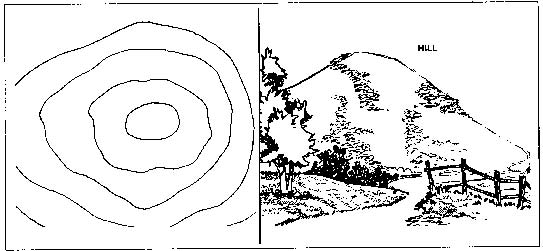
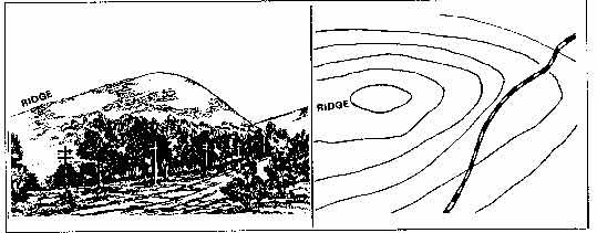
An area of high ground. Contours form concentric circles. Elevation increases toward the center.

Photograph showing a hill terrain feature with surrounding landscape
Hill (Photo)
Contour map representation of a hill showing concentric closed contour lines
Hill (Contour)

Valley

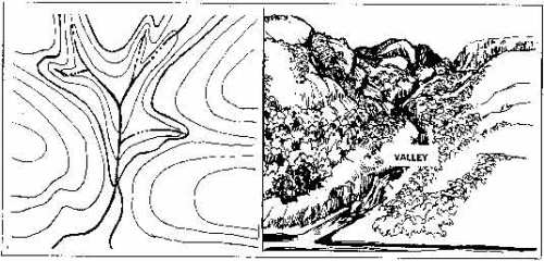
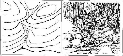
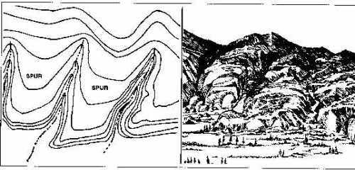
Stretched-out groove in the land. Contour lines form a U or V pointing uphill toward higher ground.

Photograph showing a valley terrain feature between hills
Valley (Photo)
Contour map representation of a valley showing U-shaped contour lines
Valley (Contour)

Ridge & Saddle

Ridge

A sloping line of high ground. Contour lines form a U pointing away from high ground (downhill).

Photograph showing a ridge terrain feature extending from high ground
Ridge (Photo)
Contour map representation of a ridge showing elongated U-shapes pointing downhill
Ridge (Contour)

Saddle

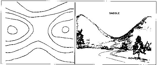
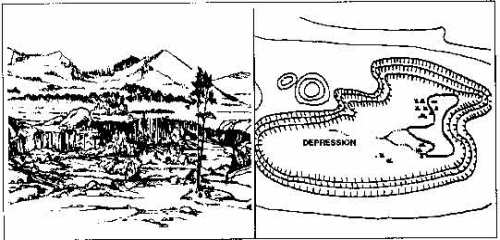
A dip or low point between two areas of higher ground. Resembles an hourglass on the map.

Photograph showing a saddle terrain feature between two hills
Saddle (Photo)
Contour map representation of a saddle showing hourglass pattern between two sets of concentric contours
Saddle (Contour)

Depression & Minor Terrain Features

Depression (Major)

Low point surrounded by higher ground. Like a hill but with tick marks pointing inward (downhill).

Photograph showing a depression terrain feature
Depression (Photo)
Contour map of depression with tick marks pointing inward
Depression (Contour)

Draw (Minor)

A less-developed stream course. Contour V's point uphill. Similar to a valley but smaller.

Photograph showing a draw terrain feature
Draw (Photo)
Contour map of a draw showing V-shapes pointing uphill
Draw (Contour)

Spur (Minor)

Short continuous sloping line of higher ground jutting from a ridge. Contours point downhill.

Photograph showing a spur terrain feature
Spur (Photo)
Contour map of a spur showing U-shapes pointing downhill
Spur (Contour)

Cliff (Minor)

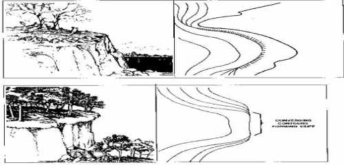
Vertical or near-vertical change in elevation. Contour lines very close together, touching, or overlapping.

Photograph showing a cliff terrain feature
Cliff (Photo)
Contour map of a cliff showing contour lines merging together
Cliff (Contour)

Supplementary Features: Cut & Fill

Cut

Man-made feature where earth has been removed (e.g., road through a hill). Tick marks point down toward the road.

Photograph showing cut and fill terrain features along a road
Cut & Fill (Photo)
Contour diagram showing cut and fill symbols along a road
Cut & Fill (Contour)

Fill

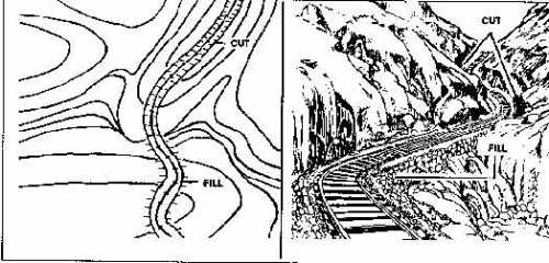
Man-made feature where earth has been added (e.g., road across a valley). Tick marks point down away from the road.

CUT = Ticks point DOWN to road
FILL = Ticks point DOWN away from road

Complete Feature Summary

5 Major (HVRS-D) + 3 Minor (Draw, Spur, Cliff) + 2 Supplementary (Cut, Fill) = 10 Total Terrain Features

Hand Terrain Association Method

Use your hand as a terrain model to remember features:

HILL (Fist/Palm) SPUR SPUR SPUR DRAW DRAW VALLEY (Between fingers) RIDGE (Knuckle line) SADDLE (Between knuckles)
  • Fist/Palm = Hill (high area)
  • Fingers = Spurs (extend from high ground)
  • Between Fingers = Draws (low areas between spurs)
  • Knuckle Line = Ridge (line of high ground)
  • Between Knuckles = Saddle (low between highs)
  • Curved Palm = Valley (wide low area)

2A: Lensatic Compass Components

Reference: TC 3-25.26, Ch. 6 | TM 9-1290-333-15

Labeled photograph of a lensatic compass showing cover, lens, bezel ring, thumb loop, and sighting wire
Labeled photograph of a lensatic compass
Lensatic Compass (Photo)
FM-style labeled diagram of a lensatic compass with all components identified
FM-style labeled diagram of a lensatic compass
Lensatic Compass (FM Diagram)

Key Components

  • Cover - protects dial, contains sighting wire
  • Bezel Ring - 120 clicks x 3° = 360°
  • Floating Dial - magnetic needle under glass
  • Fixed Black Index Line - reads azimuth
  • Lens/Rear Sight - magnifies dial for reading
  • Thumb Loop - secures compass to hand

2B: Compass-to-Cheek Method

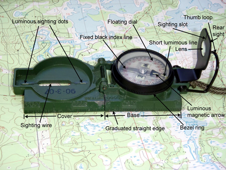
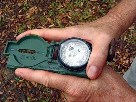
Accuracy: ±3° — Standard Method for Precision

  1. Open cover to 90° forming a straight sighting line
  2. Open lens/rear sight to 45°
  3. Place thumb through thumb loop
  4. Raise compass to cheek, sighting wire near eye
  5. Look through rear sight lens at dial while sighting target through wire
  6. Read azimuth through lens where fixed index line meets dial

When to use: Precise navigation, plotting azimuths, targeting distant objects.

Sketch showing the compass-to-cheek technique with soldier holding compass to face for sighting
Sketch
Compass-to-Cheek Sketch
Photograph showing a soldier sighting through a lensatic compass using compass-to-cheek method
Photograph
Compass Sighting (Photo)

2B: Center-Hold Method

Accuracy: ±10° — Quick Method for General Direction

  1. Open compass fully so cover is flat
  2. Hold compass at waist level, steady with both hands
  3. Point cover directly at target
  4. Look down and read azimuth at fixed index line
  5. Keep compass level throughout

When to use: Quick readings, thick vegetation, poor visibility, following a general azimuth when speed matters more than precision.

Comparison

MethodAccuracySpeedBest For
Compass-to-Cheek±3°SlowPrecision
Center-Hold±10°FastQuick reads
Sketch showing the center-hold compass technique with soldier holding compass at waist level
Sketch
Center-Hold Sketch
Photograph showing a soldier using the two-hand center-hold technique with a lensatic compass
Photograph
Two-Hand Hold (Photo)

2C: Back Azimuth

Rules

  • If azimuth < 180°: ADD 180°
  • If azimuth > 180°: SUBTRACT 180°
  • If azimuth = 180°: back azimuth = 0° (360°)

Back Azimuth Calculator

Diagram showing back azimuth concept with forward and reverse directions marked on a compass rose
Diagram
Back Azimuth Diagram

2D: Declination Diagram

The declination diagram shows angular relationships between the three norths. This is critical for converting between grid and magnetic azimuths.

Three declination diagram examples showing different angular relationships between Grid North, True North, and Magnetic North
Three declination diagram examples
Declination Diagram Examples
Diagram showing the three norths - Grid North, True North, and Magnetic North with their angular relationships
Diagram
Three Norths

Three Norths

  • True North (TN) - Direction to the North Pole. Marked with a star.
  • Grid North (GN) - Direction of the grid lines on the map. Marked with "GN".
  • Magnetic North (MN) - Direction the compass needle points. Marked with half-arrow.

2E: G-M Conversion Rules

ConvertingMN DirectionOperation
Grid → MagneticMN East of GNADD G-M angle
Grid → MagneticMN West of GNSUBTRACT G-M angle
Magnetic → GridMN East of GNSUBTRACT G-M angle
Magnetic → GridMN West of GNADD G-M angle

G-M Angle Converter

Diagram showing Grid to Magnetic azimuth conversion process
Diagram
Grid to Magnetic
Diagram showing Magnetic to Grid azimuth conversion process
Diagram
Magnetic to Grid

3A: Dead Reckoning

Dead reckoning is navigating from a known point using a known direction and known distance. It is the foundation of all land navigation. (TC 3-25.26, Ch. 9)

1. Known Starting Point

Grid coordinate, terrain feature, or previous nav point. Without this, nothing else works.

2. Known Direction

Magnetic azimuth from compass. Always convert grid to magnetic using G-M angle.

3. Known Distance

Measured from map, tracked by pace count in the field.

Complete Dead Reckoning Procedure (8 Steps)

  1. Identify start point on map and ground
  2. Plot destination on the map
  3. Determine grid azimuth using protractor
  4. Convert to magnetic azimuth (G-M angle)
  5. Measure distance on map using scale
  6. Calculate pace count for that distance
  7. Set compass to magnetic azimuth (bezel ring)
  8. Navigate: walk on azimuth, count paces

3B: Pace Count

Determining Your Pace Count

  1. Measure a 100-meter course on flat terrain
  2. Walk counting every time your left foot strikes ground
  3. Repeat 3 times and average
  4. Average = your pace count per 100m

Note: 1 pace = same foot hits ground (2 steps). Typical: 60-70 paces/100m.

Adjustment Factors

FactorConditionAdd
SlopeSteep up/downhill+5 to +10
VegetationThick brush+2 to +10
SurfaceSand, mud, snow+5 to +10
LoadHeavy ruck+2 to +10
WeatherWind, rain+3 to +5
FatigueExtended movement+3 to +8

Pace Count Calculator

Ranger Beads

  • Lower 9 beads = 100m each
  • Upper 4 beads = 1,000m each
  • After one pace count: pull 1 lower bead
  • After 9 lower (900m): pull 1 upper, reset lower
  • Tracks up to 4,900m

3C: Navigation Aids

Attack Point

Navigate to a large, easily identifiable feature near your objective. Then make a short, precise movement to the target.

Example: Navigate to a hilltop (attack point) near your actual objective, then walk a short precise azimuth to the point.

Handrail

Follow a linear feature (road, stream, ridge, power line) that runs roughly parallel to your direction of travel. Reduces navigation error.

Example: Follow a stream that runs roughly toward your destination.

Catching Feature

A large, unmistakable feature beyond your objective. If you reach it, you know you have gone too far and need to turn back.

Example: A major road 200m past your objective.

Diagram showing the technique for bypassing an obstacle during land navigation using 90-degree turns
Bypassing an Obstacle
Diagram showing the deliberate offset technique where the navigator aims to one side of the objective intentionally
Deliberate Offset

3D: Intersection

"I know where I am. Where is THAT?"

  1. From known position A, shoot azimuth to unknown target
  2. Convert to grid azimuth and plot line on map
  3. Move to known position B
  4. Shoot azimuth to same target, convert, and plot
  5. Where the two lines cross = target location

Key Points

  • Requires 2+ known positions
  • Both positions must have line of sight to the unknown point
  • Best angle between lines: 60°-120°
  • Used to locate: enemy positions, distant landmarks, targets
Map diagram showing the intersection technique with two known positions shooting azimuths to locate an unknown point
Map diagram
Intersection on Map

3D: Resection

"I know what THOSE are. Where am I?"

  1. Identify 2+ known landmarks on the map and on the ground
  2. Shoot magnetic azimuth to landmark A
  3. Convert to grid azimuth, compute back azimuth
  4. Plot back azimuth line FROM landmark A on map
  5. Repeat for landmark B
  6. Where lines cross = your position

Key Points

  • Requires 2+ identifiable landmarks
  • Uses back azimuths (not forward azimuths)
  • Best angle between lines: 60°-120°
  • Used when you are lost or need to confirm position
Map diagram showing the resection technique with back azimuths plotted from two known landmarks intersecting at the navigator's unknown position
Map diagram
Resection on Map

Block 4: CST Land Navigation Preparation

Cadet Summer Training (CST) at Fort Knox includes a land navigation assessment. These are verified requirements based on 2022-2025 sources.

RequirementDetailsStatus
Day Navigation~4 points, ~4 hours, find 3/4 to passVERIFIED (2022-2025)
Night Navigation~2 points, ~2 hours, find 1/2 to passVERIFIED
Written Test70% minimum to passVERIFIED
RECONDO90%+ written, 5/6 points combinedVERIFIED
EquipmentCompass, map, protractor, pencil, red-lens flashlightVERIFIED
CST 2026 specific policy memo not yet published - requirements may vary from previous years.

Skills Mastery Checklist

Track your readiness. Check off each skill as you master it:

0 / 10 skills mastered

Jeopardy Review Game

3 Key Takeaways

1. Always Convert Grid to Magnetic

The #1 cause of navigation failure is forgetting to convert between grid azimuth (from the map) and magnetic azimuth (for the compass). Always apply the G-M angle before stepping off.

2. Know Your Pace Count

Your pace count is your distance meter in the field. Without an accurate, practiced pace count adjusted for terrain and load, you cannot dead reckon effectively. Practice before CST.

3. Use Terrain Association

Do not rely solely on azimuth and pace count. Continuously compare the terrain around you to the map. Use attack points, handrails, and catching features to confirm position.

Study & Exam Resources

Exam Instructions

The written exam covers all four blocks of instruction. Minimum passing score is 70%. RECONDO standard is 90%+.

Study Guide & Exam

Primary Reference: TC 3-25.26, Map Reading and Land Navigation, Nov 2013

CDT Mbagwu | TAC 1 | CCNY Empire Battalion ROTC | 2nd "Freedom" Brigade

13 MAR 2026